Downlinks
Downlink control messages
Downlink messages can be used to enable, disable or reconfigure specific features of the ioTracker. For the ioTracker 3 a downlink message is only sent to the ioTracker by the LoRa network in response to an uplink message. For the ioTracker 3 Pro this functionality has to be implemented at the server side. There a two types of downlinks and in some cases it's possible to combine them.
-
Feature control downlinks to start and stop features
-
Action header downlinks to make specific configuration changes
CRC of the last downlink
With this feature, the server can verify whether a downlink messages was successfully received by the ioTracker. The CRC value is the XOR of all the received bytes (the LoRa/cellular “payload”) of the last downlink which has been received.
Feature control downlinks
| B0 | B1 | B2 | B3 | B4 | B5 | B6 | ||
|---|---|---|---|---|---|---|---|---|
| Downlink header (5b) | Feature contol (3b) | Buzzer sequences (4b) | LED sequences (4b) | LED color (8b) | Find timer | Find duration timer | Default timer | Alive timer |
Downlink header (B0)
The first 5 bits of the downlink header defines the downlink type.
| value | description |
|---|---|
| 0 | Defines a feature control downlink |
| 2 | Defines a action header downlink |
Feature control (B0)
The next 3 bits defines the feature controls
| bit position | default value | description |
|---|---|---|
| b0 | 0 | Enable (1) or disable GPS (0) |
| b1 | 1 | Enable (1) or disable all onboard sensors (0) |
When b1 is set on disable, all sensors will be stopped. If b1 is set on enable, all onboard sensors will be enabled if they are also set on enabled in their sensor specific configuration.
Feature control examples
Start a GPS session
07030F021E0A1E [CRC 03]
Behaviour (default configuration):
-
GPS will be started, searching up to 5 minutes for a valid position.
-
While the device is moving GPS will stop after 60 minutes or GPS will stop after 15 minutes without movement.
Also controlled with this downlink: 1. (0x0A) The normal timer will be changed to 10 minutes
-
(0x1E) The alive timer will be changed to 30 minutes
-
All the onboard sensors will be enabled (if they are configured to be enabled in their specific config)
-
A new LED sequence is started (to indicate GPS is on)
-
If sound was on (running buzzer sequences), those are stopped.
-
Find mode is activated for a half hour, thus for the upcoming half an hour an uplink is send every 2 minutes, only then it will go to the 10 / 30 timers. If GPS stops before this half hour find mode will continue to send data every 2 minutes, but then without the GPS data. If GPS stops later then this half hour, GPS will continue to send every 2 minutes, but when stopped it will go to the 10/30 timer immediately
Enable buzzer alarm on device for 30 minutes
0673F0021E0A1E [CRC 8D]
Sequences
Buzzer sequences (B1)
The first 4 bits defines the buzzer sequences
| value | description | extra information |
|---|---|---|
| 0 | Stop current running buzzer sequence | |
| 1 | A-Team | |
| 2 | AxelF | |
| 3 | Melody 1 (Join melody) | |
| 4 | Wakeup 1 (alarm clock sound) | looped |
| 5 | Sirene_1 (ramp up) (fire alarm) | looped |
| 6 | Sirene_2 (ramp up, ramp down) | looped |
| 7 | Find_1 (energy efficient beeps) | 1 hour (default) |
| 8..15 |
LED sequences (B1)
The next 4 bits defines the LED sequences
| value | description | sequence | runtime in seconds |
|---|---|---|---|
| 0 | Stop current running LED sequence | ||
| 1 | Fast blink | 3 x blink (100/400 ms), wait 2 sec, x4 | 6 |
| 2 | Very fast blink | 5x blink (25/100 ms), wait 2 sec, x10 | 29,250 |
| 3 | 3 medium continuous blinks | 3x blink (33/300 ms), wait 1 sec, x1800 | 1 hour |
| 6 | 2 medium continuous blinks | 2x blink (100/400 ms), wait 1 sec, x1800 | 1 hour |
| 7..15 |
LED colour (B2)
The intensity of the LED can be set for the LED sequence
| value | description | extra information |
|---|---|---|
| 4b | Red LED intensity | 0..15 (where 0 is off and 15 is full on) |
| 4b | Green LED intensity | 0..15 (where 0 is off and 15 is full on) |
Timers (B3..B6)
The ioTracker operations are time based and are divided in four different timers. The timers determine the moment that an uplink will be send.
| byte position | description | default |
|---|---|---|
| 3 | Find timer (temporary timer for find operations like GPS) | 2 minutes |
| 4 | Find duration timer (maximum time find timer is active) | 0 hour |
| 5 | Default timer (update interval when movement is detected) | 20 minutes |
| 6 | Alive timer (update interval when no movement is detected) | 60 minutes |
When the find duration timer (set via byte B4) is activated, the device uses the find timer (set via byte B3) for operation. When the find duration timer is expired (or written with 0x00) the device timer uses the default timer byte (set via byte B5) when moving and the alive timer (set via byte B6) when not moving (static).
When the GPS function is active the ioTracker automatically uses the find duration timer to send an uplink every 2 minutes (unless configured differently). The find timer should therefore be configured only to 2 or 3 minutes. Each timer (as referred to in previous table and represented by byte 3, 4, 5 or 6), is either interpreted as minutes or as hours. This is explained in the table below;
| bit position | description |
|---|---|
| b0..b6 | Timer value |
| b7 | When the value is 0, b0..b6 should be read as minutes. When the value is 1, b0..b6 should be read as hours |
Timer value examples
| timer | value |
|---|---|
| 2 minutes | 0x02 |
| 5 minutes | 0x05 |
| 10 minutes | 0x0A |
| 30 minutes | 0x1E |
| 60 minutes | 0x3C |
| 1 hour | 0x81 |
| 4 hours | 0x84 |
1 hour in minutes and 1 hour in hours will result in equal timing.
Timer examples
Change normal timer to 10 minutes and the alive timer to 30 minutes, with enabling find mode for 30 minutes (default)
060000021E0A1E [CRC 0E]
Behaviour (default configuration):
-
(0x0A) The normal timer will be changed to 10 minutes (timer when the device is moving)
-
(0x1E) The alive timer will be changed to 30 minutes (timer when the device is not moving)
Also controlled with this downlink:
-
All onboard sensors will be enabled (if they are configured to be enabled in their specific config)
-
GPS will be stopped, if it was running
-
LED sequence will be stopped, if any were running
-
Buzzer sequences will be stopped, if any were running
-
Find mode is activated for half an hour, thus for the upcoming half an hour an uplink is send every find timer minutes (2 minutes by default). Consecutively, the ioTracker will go back to normal operation using the configured normal (10 minutes) and alive (30 minutes) timer values.
Change normal timer to 10 minutes and the alive timer to 30 minutes, without enabling find mode
06000002000A1E [CRC 10]
This downlink results in the same behavior then the previous one, except it doesn't activate the find duration timer.
Action header downlinks
When the action header is set to 0x2, a configuration message can be sent to configure a specific action. Be aware that the feature control bits are included in these downlinks as well, A downlink configuration message does also start/stop GPS and or start/stop the onboard sensors. Normally, GPS is assumed to be OFF and the onboard sensors are assumed to be ON.
| B0 | B1 | Bx..By | |
|---|---|---|---|
| Downlink header (5b) | Feature control (3b) | Action | Action content |
| 00010 | xxx |
Actions
| byte position | Action | Description |
|---|---|---|
| 1 | Remote control | Reboot/Reset function |
| 2 | LoRaWAN configuration | SF, ADR etc. |
| 3 | Cellular configuration | RAT, PIN etc. |
| 12 | Button configuration | Defines the action per button mode |
| 13 | GPS configuration | Defines the GPS mode |
| 15 | Read software version | Retreive the software version |
| 16 | Silent mode | Supress all LED and buzzer signals |
| 20 | Battery level | Overwrite the current battery level |
| 22 | Light sensor configuration | Define specific light sensor configurations |
| 23 | Accelerometer | Define specific accelerometer configurations |
| 24 | Temperature sensor configuration | Define specific temperature sensor configurations |
| 25 | WiFi configration | Define specific WiFi configurations |
| 27 | Bluetooth configuration | Define specific WiFi configurations |
| 30 | Humidity and pressure configuration | Define specific humidity and pressure sensor configurations |
Remote control (1)
It's possible to reset the configuration to factory defaults. The LoRaWAN keys and the cellular endpoint configuration will remain intact.
Remote control example
Reboot without configuration changes
120102 [CRC 11]
Load configuration to factory defaults and reboot the device
120103 [CRC A0]
LoRaWAN configuration (2)
Several parameters of the LoRaWAN configuration can be changed, you can find them in the table below. B4..B5 should be included and are always 0x0A01
| bit position (B0) | description | application | default value |
|---|---|---|---|
| b0 | Set LoRaWAN config W1 | - | |
| b1 | Set LoRaWAN config W2 | - |
| bit position W1 (B0..B3) | description | application | default value |
|---|---|---|---|
| b8..10 | Minimum data rate | DR0=SF12, DR7=SF7 | 0 (SF12) |
| b11..b13 | Maximum data rate | DR0=SF12, DR7=SF7 | 5 (SF7) |
| b14..b16 | Moving data rate | Lowered to this value if SF was higher. Must not conflict with min and max DR | 2 (SF10) |
| b17..b18 | No link check after moving | 0 | |
| Do link check after moving and DR change | Aims for DR optimization | 2 (default) | |
| Link check margin for geolocation | Aims for reception at 3 gateways | 3 | |
| b19..b26 | 0..15 amount of acknowledge retries | 7 | |
| b28 | Re-join LoRa at uplink counter 16b rollover (only for OTAA) | As the device uses an internal 32b uplink counter, and rollover to (2^16)+1 might be problematic, depending on provider network settings. | 1 |
| b29 | Linkcheck on Single Click (site survey mode) | Perform a linkcheck on Linkcheck on Single Click (site survey mode), this is useful to perform site surveys. | 0 |
| bit position W2 (B0..B3) | description | application | default value |
|---|---|---|---|
| b0..b7 | Default lorawan app port | 1 | |
| b8..b15 | Demodulation margin | Margin for increasing. If SNR > 10 + (S * 3) S is steps in DataRate |
|
| b16..b21 | 0..63 LoRaWAN MAC Region |
See table below, currently only 5 and 8 are supportd | 5 |
| b22..b23 | RFU | ||
| b24..b31 | RFU | 0 |
| LoRaWAN Region | Value |
|---|---|
| AS923 | 0 |
| AU915 | 1 |
| CN470 | 2 |
| CN779 | 3 |
| EU433 | 4 |
| EU868 | 5 |
| KR920 | 6 |
| IN865 | 7 |
| US915 | 8 |
| RU864 | 9 |
Extra information
Currently 6 bytes have to be send for the complete lora config. If nbtrails is configured high enough (as default 7) for the datarate to drop during retransmission of an unacknowledged confirmed message, the datarate can drop below the configured minimum datarate. The next message will however comply again with the minimum datarate.
LoRaWAN examples
Load LoRaWAN configuration to default
1202FFA83C10010A [CRC 60]
Force the LoRa spreading factor when moving to SF12
1202FF283C10010A [CRC E0]
Force the LoRa spreading factor always to SF7
1202FF6D3D10010A [CRC A4]
Cellular configuration (3)
The information in this chapter is only applicable to our ioTracker 3 Pro cellular device.
Actions B0
| bit position (B0) | description | application | default value |
|---|---|---|---|
| b0 | Set Cellular config W1 | - | |
| b1 | Set Cellular config W2 | - | |
| b2 | Set PIN code | 0 | |
| b3 | Set URL/IP | Max 48 characters | 0 |
| b4 | Set port | 0 | |
| b5 | Return ICCID | SIM card ID | 0 |
| b6..b8 |
Set cellular config W1 B0123
| bit position (B0123) | description | application | default value |
|---|---|---|---|
| b0..3 | 1..3 nr. Of enabled RAT’s | 1: Only 3rd prio RAT is used. 2: 3rd prio is used as a start, and as a fallback. 3: Same as 2 but from 3rd is jumped to 1st, and tried, if attached it stays here, if not then it tries 2nd, if that fails it uses 3rd prio. |
3 |
| b4..7 | 3rd priority RAT | EGPRS (backup, used as other priorities can’t attach). | 9 |
| b8..b11 | 2nd priority RAT | LTE-M | 7 |
| b12..b15 | 1st priority RAT | NB-IOT | 8 |
| b16..b19 | RFU | 0 | |
| b20 | Enable PIN code | 0 | |
| b21 | 0: Set IP 1: Set URL |
URL must be resolved but more flexible. | 1 |
| b22..b23 | 1st Prio Network attach time 0: 1M 1: 2M 2: 5M 3: 10M |
2 | |
| b24..b25 | Other prio network attach time. | 1 | |
| b26 | Add COPS and CSQ to payload | 1 | |
| b27 | RFU | 0 | |
| b28..b29 | Downlink window length 0: 2s 1: 3s 2: 5s 4: 10s |
1 | |
| b30..b31 | RFU | 0 |
Set cellular config W2 B0123
| bit position (B0123) | description | application | default value |
|---|---|---|---|
| b0 | Enable NNPO NoNetworkPowerOptimazation | Don’t try to attach to network with no reception and on same location. | 1 |
| b1..2 | NdetachLimit (Nr. Of Enabled RAT’s) + 1 + N 3 + 1 + N | (2.5) After how many failed attach attempts stop trying to attach. | 1 (5) |
| b3..b5 | TryStatic 1 << (1 +N) | (2..255) Try every Nth packet anyway to see if network recovered If configured at 7, it will never try static. | 4 (32) |
| b6 | Auto update and load IP | b21 must be set to URL. The resolved URL is stored automatically in the IP field if successful and used when resolving fails. | 1 |
| b7 | While moving, try every uplink all configured RAT if no network. | More change of network connection if continuously moving. Especially if the 3rd prio RAT (the backup) does not work in every country. | 1 |
| b8..b31 | RFU | 0 |
Cellular configuration examples
Load cellular configuration to default (NB-IOT, LTE-M and EGPRS)
1203019387A015 [CRC B1]
Enable PIN code for sim card (PIN=0000)
1203019387B015 [CRC A1]
NB-IOT only
1203018188A015 [CRC AC]
LTE-M only
1203017177A015 [CRC A3]
EGPRS only
1203019199A015 [CRC AD]
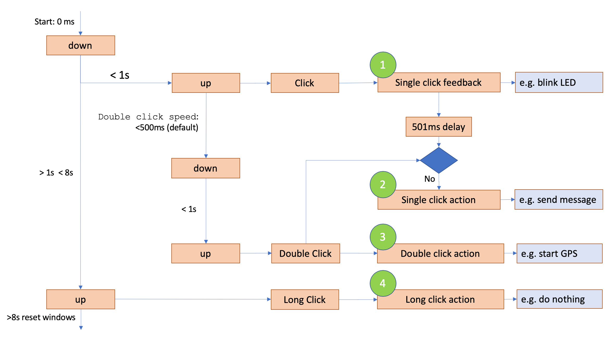
Button configuration (12)
The ioTracker supports single, double and long clicks. As a double click always starts with a single click, from computational perspective, until the second click is received, the behaviour on the first click can be configured separately (e.g., for instant audio-visual response). The second click could then start a specific action, e.g., start GPS.
There are four functions which can be configured to do actions, i.e.:
-
Single button audio-visual feedback (“Single click feedback”)
-
Single button action (“Single click action”)
-
Double button action (“Double click action”)
-
Long button action (“Long click action”)
| byte position | description |
|---|---|
| B0 | configuration for “Single click feedback” |
| B1..B2 | configuration for “Single click action” |
| B3..B4 | configuration for “Double click action” |
| B5..B6 | configuration for “Long click action |
There is an additional option to ensure that a single click is not executed when you do a double click. This is indicated by the colomn "single w/o double click" and " single with double click" in the table below.
B0 / B1 / B3 / B5 – Function 1, 2, 3 and 4
| bit position | single w/o double click | single with double click | double | long | description | application |
|---|---|---|---|---|---|---|
| b0 | - | 1 | 1 | 0 | button pressed stops the duration timer | |
| b1 | - | 0 | 0 | 0 | button pressed starts the duration timer | Increased messaging for, e.g., combination with GPS |
| b2 | - | 0 | 0 | 0 | button pressed disables the GPS (if running) | |
| b3 | - | 0 | 0 | 0 | button pressed enables the GPS (if off) | emergency button with geolocation function |
| b4 | 1 | 0 | 1 | 0 | button pressed stops running LED sequences and start sequence 4 (single flash) | |
| b5 | 0 | 0 | 0 | 0 | Button pressed stops running LED sequences and start LED sequence 3 (Medium continues notification) (downlink with buzzer overwrites current running) (sets color 0x0F: Green) | Can be used to flash the LED when GPS has been activated via the button |
| b6 | 1 | 0 | 1 | 0 | button pressed stops running buzzer sequences and start sequence 8 (Single beep) | |
| b7 | 0 | 0 | 0 | 0 | button pressed stops running buzzer sequences and start sequence 7 (battery saving nice beeps) (downlink with buzzer overwrites current running) | |
| b8..b9 | - | - | 3 | - | Double Click speed 0: 700ms 1: 1000ms 2: 1500ms 3: 2000ms |
|
| b10 | - | - | - | - | RFU | |
| b11 | - | 1 | 1 | 0 | button is send as confirmed LoRa message | emergency button function; increases the probability that an uplink as a result of a button press is received by the application server by trying to send the uplink 8 times if no ACK is received from the network. |
| b12 | - | 1 | 1 | 0 | button pressed sends a LoRa uplink message depending on the button type, the uplink reason is set accordingly. | disable sending a LoRa packet and only execute action |
| b13 | - | 0 | 0 | 0 | Bluetooth is activated and discoverable | led starts blinking blue, you can connect with the APP |
| b14 | - | 0 | 0 | 0 | Bluetooth stops advertising and disconnects | |
| b15 | - | 0 | 1 | 0 | Set "uplink reason GPIO" in uplink message | To indicate this click action |
Button configuration examples
Button configuration to default (no long press and double click activates GPIO bit)
120C5018019B510000 [CRC 9D]
Button configuration to enable GPS on single click (event 1.)
120C50180995B10000 [CRC 7B]
Button configuration to single + 1-second longclick. No confirmation beep
120C1018019B119811 [CRC 14]
GPS configuration (13)
The GPS configuration can be changed via B0..B3. The timers are seperated from the normal system timers. The GPS duration moving timer is changed via B4 and the GPS alive timer with B5.
Note: GPS is not started using this downlink (only configured). After (re)configuring GPS, you need to send a feature control downlink to enable GPS.
| bit position (B0..B3) | description | application | default value |
|---|---|---|---|
| b0 | single FIX (GPS stops on first valid fix) | less battery usage for stationary/nomadic applications | 0 |
| b1 | - | - | 1 |
| b2 | - | - | 1 |
| b3 | - | - | 1 |
| b4 | - | - | 0 |
| b5 | - | - | 1 |
| b6 | - | - | 1 |
| b7 | Enable extra time to reach configured accuracy goal for first fix | increase accuracy | 1 |
| b8..b10 | Allowed time to reach first fix (at least 3 satellites) 0: 90s 1: 180s 2: 300s 3: 420s 4: 600s |
2 | |
| b11..b13 | Allowed time to reach subsequent fix (at least 3 satellites) 0: 20s 1: 40s 2: 70s 3: 120s 4: 180s 5..7: RFU |
2 | |
| b14..b15 | Allowed extra time to reach configured accuracy goal 0: 10s 1: 20s 2: 30s 3: 40s |
lengthen GPS on time if FIX or 3SV but accuracy is desired to be higher. | 3 |
| b16..b19 | Accuracy goal. Send the position with this accuracy is beter then configured value 0 .. 15 * 10m |
default GPS on time is lengthened if hacc > value (default 30m) | 3 |
| b20 | Enable GPS on boot enable on startup |
for applications with GPS always enabled | 0 |
| b21 | Start on Timer Start GPS every x period |
Single fix by default | 0 |
| b22..b23 | - | - | 0 |
| b24 | when 0SV and time to first fix (max) is reached, send anyway | never stop after 1st fix when lost GPS reception | 0 |
| b25 | max performance GPS | for increased accuracy, adds less time to timer, thus faster uplinks. Drains the battery faster. | 0 |
| b26 | enable GPS always on | keep GPS always on | 0 |
| b27 | enable on movement | start GPS automatically when the accelerometer detects movement. | 0 |
| b28 | enable on static position (more robust) | enables GPS when not moving (sync after configurable #messages moved/not moved). Must not be enabled when b5 is 1. | 0 |
| b29 | enable on static position | enables GPS when not moving (async/directly). must not be enabled when b4 is 1. | 0 |
| b30 | button reset for both “enable on static position” features | resets the state of the position algorithm to initial state, giving you 5 seconds to lay down/still the ioTracker, as otherwise a movement will be triggered when pressing the button again. | 0 |
| b31 | disable GPS below temperature | does not start GPS if the temperature is below xx degrees (default is -10°C). | 1 |
Note 1: If "enable on static position (more robust)" (b4) is enabled, then two more bytes have to be send:
-
B6 = steady counter limit (default 2)
-
B7 = move counter limit (default 2)
Note 2: If "enable on static position function" (b5) is enabled, then one more byte has to be send:
- B6 = steady counter timer value(default 10m=0x0A)
Note 3: If "disable GPS below Temperature" (b7) is enabled, then one more byte has to be send:
- B6 = signed char(8b) (temperature in °C) in whole degrees. Default = 0xFB -> -10°
Note 4: If "GPS Start Timer (b21)" is enabled, then one more byte has to be send:
- B6 = signed char(8b) A new GPS Start is initiated every x time. This timer uses the Timers V2 calculation.
- Default = 0x3B -> 24 hours, 26 minutes and 40 seconds.
- Enable on startup should also be set in order to be started, otherwise it has to be started with any other gps starting event.
- Timer starts at the end of last gps message, timer reset with any gps starting event.
GPS configuration examples
Configure GPS stays always on
120D0502CAEE0F81 [CRC B2]
120D0512CAEE0F81 [CRC A2] (enable on boot)]
Configure GPS to stop after first GPS message
120D0002CAEF0F81 [CRC B6]
Configure GPS to start on moving
120D0902D2EE0F81 [CRC A6]
120D0912D2EE0F81 [CRC B6] (enable on boot)]
Configure GPS to start on moving with max performance
120D0B02D2EE0F81 [CRC A4]
120D0B12D2EE0F81 [CRC B4] (enable on boot)]
Read software version (15)
Returns next uplink message with an action header with the versioning
| byte position (B15) | description |
|---|---|
| B0 | marjor software version |
| B1 | minor software version |
| B2..B3 | firmware build number |
| B4 | Hardware version |
Read software version example
Request hardware and software version information
120F [CRC 1D]
Advanced config 2 (16)
Special advanced configuration settings.
| bit position (B16) | description | value |
|---|---|---|
| b0 | LED | 1 is silent, 0 is normal |
| b1 | buzzer | 1 is silent, 0 is normal |
| b5 | Start GPS when high temperature treshold is tripped | 1 is on, 0 is off |
Battery level (20)
There a couple of parameters to tune or correct the battery level.
| bit position (B0) | description | application | default value |
|---|---|---|---|
| b0 | - | - | - |
| b1..b2 | 0: - 1: reset battery penalty 2: Reset battery status including penalty 3: RFU |
Set all stats to 0 and battery level to full | 0 |
| b3 | change the battery level to this value. next byte (B0) is the desired level | when 0 do not send the data byte | 0 |
| b4 | - | - | 0 |
| b5 | auto reset battery level when battery was removed and replaced | (n/a for IOT3 Pro, should be 0 for IOT3 Pro) | 1 |
| b6 | - | - | 0 |
| b7 | - | - | 1 |
Battery correction (only required when b3 of B0 is set)
| byte position (B0) | description | application | default value |
|---|---|---|---|
| B0 | set battery level (correction) | Adjust current battery level to this level (for reset it's preferred to use b1 of b0) | - |
Battery level examples
ioTracker 3 reset to full
1214A4 [CRC A2]
ioTracker 3 reset to 95%
1214A8F1 [CRC 5F]
ioTracker 3 Pro reset to full
121404 [CRC 02]
ioTracker 3 Pro reset to 95%
121408F1 [CRC FF]
Light sensor (22)
The light sensor can be configured with absolute or relative limits, when the limit is reached an uplink will be send immediately.
| bit position (B0) | description | application | default value |
|---|---|---|---|
| b0 | absolute or relative limit | 0 = absolute 1 = relative | 0 |
| b1 | sensor status | 0 = disabled 1 = active | 1 |
| b2..b6 | RFU | ||
| b7 | IRQ_latch | Hold highest/lowest sensor value when threshold is exceeded (cleared with every uplink) | 1 |
Extra information
-
When b0 is not set (configured as absolute limits), the limits are 16b high and 16b low, same 4b exponent and 12b value as light.
-
When b0 is set (configured as relative limits), the limits are in percent (ranging from 1 to 254%).
-
The sensor is started or stopped depending on b1, automatically enabling the onboard sensor bit.
-
IRQ_Latch holds the highest or lowest recorded value when exceeding the threshold up until the data is transmitted. Even if the value drops below the threshold again. When going even further over the threshold the value is updated though.
[B1] Poll time in seconds
| bit position (B1) | description | application | default value |
|---|---|---|---|
| b1 | poll_time in seconds | 0x37 |
[B2..B5] Absolute limits for light sensor interrupts (applicable if b0 = 0 in B0)
| data type | description | application | default value |
|---|---|---|---|
| uint16 | an_IRQ_high | When value > high interrupt is generated [B2..B3] | 0xBFFF |
| uint16 | an_IRQ_low | When value < high interrupt is generated [B4..B5] | 0x0000 |
[B2..B3] Relative limits for light sensor interrupts (applicable if b0 = 1 in B0)
| data type | description | application | default value |
|---|---|---|---|
| uint8 | an_IRQ_high | Percentage changed from previous up (max 255%) [B2] | 0x10 |
| uint8 | an_IRQ_low | Percentage changed from previous down (max 99%) [B3] | 0x10 |
The trigger angle (rate of late change) depends on both the poll_time and the relative limit, so both have to be tuned to the desired behaviour; it is the percentage of change relative to the previous measurement. If the relative value is 0 then for that direction the limit is disabled.
Light sensor examples
Disable light sensor
12168037BFFF0000 [CRC 84]
Enable light sensor (default)
12168237BFFF0000 [CRC F1]
Enable light sensor Enable light sensor (uplink upon 50% change within 2 subsequent measurements, 5 seconds apart)
121683053232 [CRC 82]
Enable light sensor (uplink upon passing 400 lux limit, high and low)
1216820549C449C4 [CRC 83]
Accelerometer (23)
There a couple of parameters to tune the behavior of the accelerometer. It's also possible to add the XYZ position to the onboard sensors (payload).
| bit position (B0..B3) | description | application | default value |
|---|---|---|---|
| b0 | include device position (XYZ) | measure the position, expressed in X-, Y- and Z-axes | 0 |
| b1 | sensor status | 0 = disabled 1 = active | 1 |
| b2..b4 | add maximum measured force: 0: never (shorter payload) 1: since last message only 2: since last 2 messages 3: since last 4 messages 4: since last 8 messages 5: since last 16 messages 6: since boot (reset by accelerometer sensor AH downlink) 7: RFU |
shock detection and auditing | 5 |
| b5..b6 | Full-Scale selection (only for shocks): 0: +-2g 1: +-4g 2: +-8g 3: +-16g |
the result is the measured value can result up to 1.41 times full-scale, depending on the angle of the force | 3 |
| b7 | RFU | ||
| b8..b9 | ODR (Output Data Rate): 0 : 1Hz (2uA) 1 : 10Hz (3uA) 2: 25Hz (4uA) 3: 100Hz (10uA) |
faster response, more power usage | 1 |
| b10..b11 | high-pass cut-off frequency selection: 00: ODR/ 50 01: ODR/125 10: ODR/250 11: ODR/500 |
filter out slow movement. (11 => maximum sensitivity) | 0 |
| b12..b15 | INT1_THS 0..15 -> 16mg/LSB (at 2g FS) |
default 4 = 64mg | 4 |
| b16..b17 | INT1_Duration 0..3 -> Duration of event to be recognized. Time = N/ODR |
default = 1 -> 2 successive samples need to be above the threshold | 1 |
| b18..b19 | SHOCK ODR (Output Data Rate): 0: 10Hz 1: 50Hz 2: 200Hz 3: 400Hz |
faster response, more power usage | 2 |
| b20..b21 | SHOCK INT1_Duration 0..3 -> Duration of event to be recognized. Time = N/ODR |
default = 0 -> 1 sample need to be above the threshold. Multiple high readings are less easy to trigger. | 0 |
| b24..b26 | repeated move measurements | number of consecutive movements required for movement detection | 2 |
| b27..b29 | inhibit time in seconds, in between move measurements | takes into account the inhibit time between consecutive movements. Higher number results in less sensitive movement detection | 5 |
The accelerometer can be used for 3 measurements, absolute value (xyz), movement, and detect the maximum force (shock).
-
If b0 is set, the accelerometer is configured just before a message is sent to measure absolute values, it is sampled and re-configured to measure movement.
-
When movement occurs, the value is read and shock config is loaded.
-
Every shock larger than the previous, the shock threshold is updated to trigger for larger shocks.
With every message, the cycle (i.e., the three steps above), is repeated.
Accelerometer examples
Disable accelerometer
12172A094174 [CRC 13]
Enable accelerometer (default)
12172A094176 [CRC 11]
Disable XYZ (default)
12171A094176 [CRC 11]
Enable XYZ
12171A094177 [CRC 46]
Set high sensitivity accelerometer
12172A094162 [CRC 05]
Set medium sensitivity accelerometer
12172A0AF162 [CRC B6]
Set low sensitivity accelerometer
12172A0BF162 [CRC B7]
Shock Configuration (32)
Shock detection does not add additional data because the information is already available in Accelerometer max. Be sure too add the accerometer max data to the payload in the accelerometer sensor configuration.
| bit position (B0..B3) | description | application | default |
|---|---|---|---|
| b1 | 0: No shock detection 1: Shock tiggers 1 additional uplink 2: Shock tiggers always an uplink up till duty cycle limit 3: RFU |
0 | |
| b2 | Confirmed uplink? (only allowed for 1) | -- | 0 |
| b3..b15 | RFU | ||
| b16..b31 | Shock threshold | 1mg / lsb |
Note:Configure Shock history as enabled in Accelerometer config otherwise the shocks are not enabled.
Tilt Configuration (33)
When tilt is enabled, the calibration is automatically applied to the accelerometer XY (Z) data.
| Bit position (B1234) Advanced accelerometer config | description | application | default |
|---|---|---|---|
| b0 | 0: No Tilt detection 1: Tilt limit tiggers uplink |
0 = sensor disabled (move does not work anymore) | 0 |
| b1 | Confirmed uplink | 0 | |
| b2..b3 | RFU | ||
| b4 | 0: XY limits are hard, tilt zone is an upside-down square pyramid. 1: XY limits are converted to a vector, tilt zone is an upside-down cone. |
For setting 1 to work the tracker has to be mounted upright and the calibration, boundaries and calculations do not work if too angled (mounted within 10 degrees) | 1 |
| b5..b7 | Add angle information as angle sensor of the last: 0: off 1: last message only 2: last 2 messages 3: last 4 messages 4: last 8 messages 5: last 16 messages 6: over all messages (reset by Accelerometer sensor AH downlink 7: RFU |
Device has to be upright to function. | 0 |
| b8 | Re-calibrate tilt calibration | This calibrates X and Y axis, so the resulted XY angle ater calibration is 0 degrees. | 0 |
| b9..b10 | 0: No new threshold (keep old if available) 1: New position threshold in XYZ (12 Bytes) 2: New position threshold in angle (2 bytes) 3: RFU |
Setting 2 sets b4 to work in a vector. | 0 |
| b11..b14 | Tilt hysteresis: 0: 0 degrees 1: 0.1 degrees 2: 0.2 degrees 3: 0.5 degrees 4: 1 degrees 5: 2 degrees 6: 5 degrees 7: 10 degrees 8: 20 degrees 9: 30 degrees 10: 40 degrees 11: 50 degrees 12: 60 degrees |
Hysteresis is added to the tilting back motion. If b4 is set the hysteresis is auto limited to half the threshold. |
0 |
| b15 | 0: Single edge triggering 1: Double edge triggering |
Single is from valid position to go over the threshold and thus alarm. | 1 |
| b16..b19 | Filter size 2^n 1..4 allowed |
4 | |
| b20 | Use angle limits based on calculated angle instead of XYZ limits. (autoset with angle limit over 45 degrees) |
Works (better) at more then 45 degree tilt and mandatory for upside down. | 1 |
| b21..b31 | RFU |
New Threshold configuration when b9..b10 is 1
With controlling all 6 parameters and odd shaped limit box can be defined. For normal use cases use the easier configuration (angle limit, B5..B6).
| Byte position (B5..B16) XYZ threshold (optional) | description | application | default |
|---|---|---|---|
| B2..B3 | -1000..+1000mg | X Lower limit / Circle radius | |
| B4..B5 | -1000..+1000mg | X Upper limit | Ignored if b4 is set to radius |
| B6..B7 | -1000..+1000mg | Y Lower limit | Ignored if b4 is set to radius |
| B8..B9 | -1000..+1000mg | Y Upper limit | Ignored if b4 is set to radius |
| B10..B11 | -1000..+1000mg | Z Lower limit | |
| B12..B13 | -1000..+1000mg | Z Upper limit |
New Threshold configuration when b9..b10 is 2
| Bit position (B5..B6) XYZ threshold (optional) | description | application | default |
|---|---|---|---|
| B5..B6 | 0..900 | Angle limit | 0 |
Tilt sensor examples
Set angle limit to 5 degrees
122100000064910032 [CRC F4]
Calibrate
12210000006191 [CRC C3]
Temperature sensor (24)
The temperature sensor can be configured with absolute limits, when the limit is reached an uplink will be send immediately.
| bit position (B0) | description | application | default value |
|---|---|---|---|
| b0 | RFU | ||
| b1 | sensor status | 0 = disabled 1 = active | 1 |
| b2..b6 | RFU | ||
| b7 | IRQ_latch | Hold highest/lowest sensor value when threshold is exceeded (cleared with every uplink) | 1 |
Extra information
- The sensor is started or stopped depending on b1, automatically enabling the onboard sensor bit.
- IRQ_Latch holds the highest or lowest recorded value when exceeding the threshold up until the data is transmitted. Even if the value drops below the threshold again. When going even further over the threshold the value is updated though.
[B1] Poll time in seconds
| bit position (B1) | description | application | default value |
|---|---|---|---|
| b1 | poll_time in seconds | 0x0A |
[B2..B5] Absolute limits for temperature sensor interrupts
| data type | description | application | default value |
|---|---|---|---|
| uint16 | an_IRQ_high | When value > high interrupt is generated [B2..B3] | 0x2700 |
| uint16 | an_IRQ_low | When value < high interrupt is generated [B4..B5] | 0x0000 |
Extra information The temperature is defined with 2 bytes in total, where the temperature information (int16_t 0,01C / LSB ) is represented in degrees Celsius. Example: 0x075F = 18,87 degrees Celsius.
Temperature sensor examples
Disable temperature sensor
1218840a27000000 [CRC A3]
Enable temperature sensor (default)
1218860a27000000 [CRC A1]
Set temperature thresholds (uplink upon +25 and -5 degrees Celsius)
121886010bb8fe0c [CRC CC]
WiFi configuration (25)
The WiFi chip can be used for sniffing WiFi networks, reporting the MAC addresses and RSSI. For the firmware and log synching features the WiFi chip can connect to an accespoint and used for internet breakout.
| bit position (B0) | description | application | default value |
|---|---|---|---|
| b0 | set Wifi Config B0123 | ||
| b1 | set WiFi SSID | 0 | |
| b2 | set WiFi password | 0 | |
| b3..b7 | RFU |
| bit position (B01) | description | application | default value |
|---|---|---|---|
| b0 | add RSSI | 1 | |
| b1..b3 | 0 = WiFi disabled 1 ..7 => Maximum number of found MAC addresses added per payload |
WiFi sniffing. 5 MAC's for LoRa and 7 MAC's for cellular is the maximum. | 0 |
| b4..b5 | 0: basic scan and send 1: send first x number of MAC addresses and send a second set when not moving. 2: equal to 1 but send a third set. 3: RFU |
0 | |
| b6 | 1: Force / Set connect wifi now 0: - |
force connect wifi if home network is found and start config and log sync and check for updates | 0 |
| b7 | 1: Set connect wifi now at startup (UL == 2) 0: wait for the first interval |
sync config and check updates at boot | 0 |
| b8..b15 | disable WiFi below temperature. signed char(8b) (temperature in °C) in whole degrees. default = 0xF6 -> -10 °C |
does not start WiFi if the temperature is below set xx degrees Celcius. Set to -128 to disable. | -25 |
| b16..b23 | Connect wifi interval 0 = disabled 1..255 * 100. Set connect flag when uplink counter surpasses every interval. |
64 | |
| b24 | Scan every uplink | 0 | |
| b25 | Set WiFi scan now even if WiFi is disabled | Can be used together with the b7 to force a firmware update request | 0 |
| b26..b28 | Automatically start GPS if: 0 = Disabled 1= No WiFi networks found 2= Less then 2 WiFi networks found 3= Less then 3 WiFi networks found 4= Less then 4 WiFi networks found 5= Less then 5 WiFi networks found 6..7= RFU |
Based on this setting, GPS is started automatically based on the WiFi scan results | 0 |
| b29..b31 | RFU |
Extra information
-
If b7 (disable WiFi below Temperature) in B0 is set, one more byte needs to be sent;
-
B1 = signed char (8b) = temperature in °C in whole degrees. Default = 0xFF -> -1 °C.
-
Maximum networks for WiFi and BLE combined is 4, otherwise the payload gets too large for LoRa. This limit isn't applicable for cellular networks.
-
Setting WiFi network and password
-
The first byte should indicate the length of the string and next should be the data. Use only allowed characters.
WiFi configuration examples
Disable WiFi
12190100000000 [CRC 0A]
Enable WiFi with sending 4 MAC+RSSI per uplink (default for ioTracker 3)
12190100000009 [CRC 03]
Enable Wi-Fi with sending 7 MAC+RSSI per uplink (default for ioTracker 3 Pro)
1219010000000F [CRC 05]
Bluetooth configuration (27)
The Bluetooth chip can be used for sniffing (UUID + RSSI) beacons. Support for iBeacon, EddyStone and AltBeacon is available. It's also possible to activate filters and trigger. For instance: when a certain beacon is present of absent, the GPS chip can be activated.
| bit position (B0) | description | application | default value |
|---|---|---|---|
| b0 | set Bluetooth scan config B1..4 | - | |
| b1 | RFU | ||
| b2 | set scan slot config | 0 | |
| b3..b7 | RFU |
| bit position (B1..B4) | description | application | default value |
|---|---|---|---|
| b0..b1 | Bluetooth scanning 0: disabled 1: scan every uplink packet 2: Scan every x seconds (config timer via B4) and send on event 3: Scan uplink and timer |
scanning on time is useful in combination with slot match. With timer only you get only scan information on match. | 0 |
| b2 | 0: scan every uplink packet 1: Scan only when moved |
applicable if b0..b1 = 1 or 3 | 1 |
| b3 | scan on button press | any type of button press | 1 |
| b4..b7 | scan time: 1+[0..15] * 200ms |
while scanning the ioTracker uses 5mA | 15 |
| b8 | RFU | ||
| b9..b11 | 1 + 0..7 => Maximum number of found beacons added to payload | 2 | |
| b12..b13 | UUID filter: 0: disabled, send only 6 bytes (last 2 bytes of UUID + 2 bytes major + 2 bytes minor) 1: disabled send full UUID 2: Filter enabled (Needed for scan slots) 3: RFU |
6 bytes is for iBeacon, last 2 bytes of UUID + major + minor If the filter is enabled (2) and no filters are configured, the UUID filter is set to disabled and it sends only 6 bytes(0). |
0 |
| b14 | report RSSI corrected with TX power of the beacon info | distance detection | 1 |
| b15 | RFU | ||
| b16..b23 | Bluetooth Scan Timer. A new scan is initiated every x time. This timer uses the timers V2 calculation. | used when b0..b1 = 2 or 3. Scan timer should be greater than scan time. Scanning a lot uses a lot of battery! Suggested to use > 30 seconds. | 0 |
| b24..b31 | int8_t Calibration correction for the ioTracker Bluetooth receive sensitivity | beacon distance calculation. A correctly calibrated beacon and ioTracker should measure -58dB at 1m. | -58 |
If the UUID filter is configured to filter enabled, the received beacon will only be reported if it matches any of the scan slots. It checks the slots from slot 1 to slot 8, and reports the first matching results. It’s important to configure the slots in a descending order of priority. The actions of only the first matching slot will be reported and executed.
Example
-
Slot 1 with slot enabled, match on present, match on size 2 (UUID + major + minor)
-
Slot 2 with slot enabled, match on absent, match on size 1 (UUID + major)
-
Slot 3 with slot enabled, filter only, match on size 0 (UUID)
If you reverse the order above, if all used beacons of interest have the same UUID, slot 2 and slot 3 will never be reached, as the wide filter (then the filter in slot 1) always matches.
Next byte indicates which slot to use.
| bit position (B1) | description | application | default value |
|---|---|---|---|
| b0..b2 | slot number = 1 + 0..7 | scan slot (2 + 1 + 20) bytes | 1 |
| b3..b7 | RFU |
After the slot number, the config and used beacon data must be sent. The length can vary according to beacon type and match on length.
Config + ([UUID + major + minor] | [id1 + id2 + id3] | [namespace + instance])
| bit position (B2..B5) | description | application | default value |
|---|---|---|---|
| b0 | enable slot | 0 | |
| b1 | stop scan on first match | a shorter scan time uses less power. Keep scanning if you want all beacons. | 0 |
| b2..b3 | beacon type 0: iBeacon 1: EddyStone 2: AltBeacon 3: RFU |
0 | |
| b4..b5 | for beacon type match on: iBeacon: 0: UUID (16B) 1: UUID + major (18B) 2: UUID + Major + Minor (20B) AltBeacon: 0: id1 (16B) 1: id1 + id2 (18B) 2: id1 + id2 + id3 (20B) Eddystone: 0: Namespace (10B) 1: Namespace + Instance (16B) |
0 | |
| b6 | add signal level strength for match. B5 is level | only valid when scanning is 2 or 3. When present then it must be higher, when absent it must be lower. | 0 |
| b7 | RFU | ||
| b8..b15 | match level | if b7 is set, then send a level | 0 |
| PRESENT | |||
| b16 | match enables GPS | 0 | |
| b17 | match disables GPS | 0 | |
| b18 | match starts LED sequence | 0 | |
| b19 | match stops LED sequence | 0 | |
| b20 | match starts buzzer sequence | 0 | |
| b21 | match stops buzzer sequence | 0 | |
| b22 | match initiates uplink | 0 | |
| b23 | RFU | ||
| ABSENT | |||
| b24 | match enables GPS | 0 | |
| b25 | match disables GPS | 0 | |
| b26 | match starts LED sequence | 0 | |
| b27 | match stops LED sequence | 0 | |
| b28 | match starts buzzer sequence | 0 | |
| b29 | match stops buzzer sequence | 0 | |
| b30 | match initiates uplink | 0 | |
| b31 | RFU |
Extra information
- Maximum networks for WiFi and BLE combined is 4, otherwise the payload gets too large for LoRa. This limit isn't applicable for cellular networks.
Bluetooth configuration examples
Disable BLE (default)
121B01C60040F5 [CRC 7B]
Enable BLE with 2 beacons, only scan when moved
121B01C60044F5 [7F]
Enable BLE with 2 beacons, only scan when moved, and scanning on button press
121B01C60044FD [CRC 77]
Slot 1 config (iBeacon, start buzzer sequence on beacon present)
121B0400201000030066D726F52DDFB9D9888B51A8001005 [CRC 21]
Slot 1 config (iBeacon, start GPS on absent of iBeacon UUID 0066D726-F52D-DFB9-D988-8B51A8001005)
121B0400050A00030066D726F52DDFB9D9888B51A8001005 [CRC 1E]
* Slot config: 121B0400050A0003
* iBeacon UUID: 0066D726F52DDFB9D9888B51A8001005
Slot 2 config (EddyStone, start buzzer sequence on beacon present)
121B040120100007793262296DDF445F6536 [CRC C1]
Slot 3 config (AltBeacon with match on major, start buzzer sequence on beacon present)
121B04022010002Bb98F6F32CA404CDB99046D500EF6834D00030001 [CRC F6]
Humidity and pressure sensor configuration (30)
The humidity and pressure sensor can be configured with absolute limits, when the limit is reached an uplink will be send immediately.
| bit position (B0) | description | application | default value |
|---|---|---|---|
| b0 | RFU | ||
| b1 | Humidity active | 0 = disabled 1 = active | 0 |
| b2 | Pressure active | 0 = disabled 1 = active | 0 |
| b3..b6 | RFU | ||
| b7 | IRQ_latch | Hold highest/lowest sensor value when threshold is exceeded (cleared with every uplink) | 1 |
Extra information
- The sensor is started or stopped depending on b1, automatically enabling the onboard sensor bit.
- IRQ_Latch holds the highest or lowest recorded value when exceeding the threshold up until the data is transmitted. Even if the value drops below the threshold again. When going even further over the threshold the value is updated though.
[B1] Poll time in seconds
| bit position (B1) | description | application | default value |
|---|---|---|---|
| b1 | poll_time in seconds | 0x0A |
[B6..B9] Absolute limits for Humidity sensor interrupts
| data type | description | application | default value |
|---|---|---|---|
| uint16 | an_IRQ_high | When value > high interrupt is generated [B2..B3] | 0x2710 |
| uint16 | an_IRQ_low | When value < high interrupt is generated [B4..B5] | 0x0000 |
[B10..B15] Absolute limits for Pressure sensor interrupts
| data type | description | application | default value |
|---|---|---|---|
| uint16 | an_IRQ_high | When value > high interrupt is generated [B2..B3] | 0x01ADB0 |
| uint16 | an_IRQ_low | When value < high interrupt is generated [B4..B5] | 0x007530 |
Humidity and pressure sensor examples
Disable humidity and pressure sensor
121E000A2904EE6C2710000001ADB0007530 [CRC C7]
Enable humidity and pressure sensor
121E860A2904EE6C2710000001ADB0007530 [CRC 41]
Enable humidity sensor
121E820A2904EE6C2710000001ADB0007530 [CRC 25]
Enable pressure sensor
121E840A2904EE6C2710000001ADB0007530 [CRC 43]
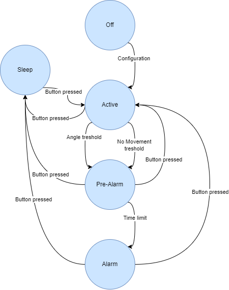
Set Man Down Detection Configuration (31)
Man Down movement detection shares the accelerometer movement detection configuration INT1_THS and INT1_Duration.
Flow-chart: Below, an abstract flowchart for state switching is displayed.
[B0] Man Down Version
B0 = Man Down version, only 0x00 supported currently.
[B1..4] Configuration
| bit position (B0) | description | application | default value |
|---|---|---|---|
| b0 | Enable angle detection | 1 | |
| b1 | Enable movement detection | 1 | |
| b2 | Enable Pre-Alarm | 1 | |
| b3 | RFU | ||
| b4..b7 | Sample speed: 0: 2 Samples per second 1: 1 Sample per second 2: 1 Sample every 2 seconds 3: RFU |
1 | |
| b8..b11 | 1+ (0..3) Position average filter. No. of samples to average 4..15 RFU |
1+(0) = off | 2 |
| b12..b15 | Default device orientation 0: upright 1..15: RFU |
0 | |
| b16..b17 | Alarm and Pre-Alarm is cancelled by: 0: Click 1: Double-Click 2: Long-Click 3: Any-Click |
If (de-)activation button is equal to the cancel button, then Man down can only be de-activated in the active state. Cancel is always before sleep. | 2 |
| b18..b19 | Man down is (de-)activated by: 0: Click 1: Double-Click 2: Long-Click 3: RFU |
If (de-)activation button is equal to the cancel button, then Man down can only be de-activated in the active state. Cancel is always before sleep. | 2 |
| b20 | Pre-Alarm by movement is cancelled by movement | 1 | |
| b21 | Pre-Alarm by angle is cancelled by going back to allowed position | 1 | |
| b22 | Alarm needs both movement AND angle, instead of either of the two (OR) | This setting will reduce the false positive rate, however, consequnetly, increases the false negative rate. In our test environment, setting this flag (AND mode) provides the best balance. | 1 |
| b22.b31 | RFU | ||
| B5 | 0..90 Angle detection threshold angle | What is the tripping point angle | 45 |
| B6 | 0..30 Angle detection time. 1 + (0..30) seconds | If you go over the threshold after how many seconds the pre-alarm will be triggered. If you go back time is reset | 4 |
| B7 | 0..255 Movement threshold in seconds | After which time of no movement the pre-alarm will be triggered | |
| B8 | 0..255 Pre-Alarm time limit | After which time of not cancelling the pre-alarm is the alarm transmitted | 20 |
All configured Man Down actions are cumulative to actions on the button config. Therefore, it is advised to keep the button action used for Man Down (e.g., long-press) free of actions in the button config (single blink and/or single beep is not problematic and, moreover, recommended to be set).
[B9] Active state actions
| bit position (B0) | description | application | default value |
|---|---|---|---|
| b0 | Enable GPS | 0 | |
| b1 | Disable GPS | 0 | |
| b2 | Start LED sequence | Default: continues LED to indicate man down is active | 0 |
| b3 | Stop LED sequence | 1 | |
| b4 | RFU | - | |
| b5 | Stop Buzzer sequence | 1 | |
| b6 | State transition initiates uplink | 0 | |
| b7 | RFU | - |
[B10] Pre-alarm actions
| bit position (B0) | description | application | default value |
|---|---|---|---|
| b0 | Pre-alarm enables GPS | 0 | |
| b1 | RFU | - | |
| b2 | Pre-alarm starts LED sequence | Starts find duration_timer for uplink every find_timer | 1 |
| b3 | RFU | - | |
| b4 | Pre-alarm starts Buzzer sequence | 1 | |
| b5 | RFU | - | |
| b6 | Pre-alarm initiates uplink | 1 | |
| b7 | RFU | - |
[B11] Alarm actions
| bit position (B0) | description | application | default value |
|---|---|---|---|
| b0 | Alarm enables GPS | 0 | |
| b1 | RFU | - | |
| b2 | Alarm starts LED sequence | 1 | |
| b3 | RFU | - | |
| b4 | Alarm starts Buzzer sequence | 1 | |
| b5 | RFU | - | |
| b6 | Alarm initiates uplink | 1 | |
| b7 | RFU | - |
[B12] (De-)activation actions
| bit position (B0) | description | application | default value |
|---|---|---|---|
| b0 | RFU | - | |
| b1 | RFU | - | |
| b2 | (De-)activation starts LED sequence | 1 | |
| b3 | (De-)activation stops LED sequence | 0 | |
| b4 | RFU | - | |
| b5 | RFU | - | |
| b6 | (De-)activation initiates uplink | 0 | |
| b7 | RFU | - |
Recommendations
- When using movement OR angle to trigger an alarm, set sensitivity of both not too high to reduce false positives:
High-pass cutoff frequencyselection atODR/250INT1_THSat3INT1_Durationat0
- When using movement AND angle to trigger an alarm, set movement sensitivity not too high to reduce false positives:
High-pass cutoff frequencyselection atODR/50INT1_THSat6INT1_Durationat1
- To avoid stopping the LED and Buzzer sequence on a normal press, set
b2andb3to0in the ioTracker advanced config.
Important
For correct function of man down you also need to configure the following:
- Advanced config:
1211000C7D83 - Accelerometer sensor config:
12172A096162 - Button config:
120C5018019B510000(default, important to have long press free as it is used for Man Down)
Man Down examples downlink
Default AND config
121F00007A02171414032D04541464 [CRC 6C]
Default AND config (1 minute movement threshold, 30 seconds pre-alarm threshold, start GPS upon alarm
121F00007A02171E3C042D04555428 [CRC 44]
Testing procedure
-
Reset the device to factory defaults with the button or downlink
-
Observe the device joining the network / sending its first message.
-
Send the first downlink.
-
Observe the next uplink has in the “CRC last downlink” field not 0x00, but the CRC of last downlink. be assured that the downlink has been received.
-
If applicable send the second downlink. Ensure the second downlink has been received by checking the CRC field again.
-
Configuration and activation is now complete. The device should now work with the new configuration and status.
-
Validating whether the ioTracker’s new behaviour matches the expected behaviour.
-
Conclude this test with a FAIL or PASS. In case of a FAIL, write down all actions and observed behaviour as unambiguously as possible
Every test this procedure should be fully repeated. If configurations need to be combined, please contact ioThings for checking compatibility.