Payload
General applications
To help developers to speedup the development process, we have published a javascript example of our payload decoder on GitHub. This example code supports the decoding of all available sensordata.
Notations
| Value | Description |
|---|---|
| xb | X number of bits required, e.g., 3b=3 bits required |
| xB | X number of bytes required, e.g., 3B=3 bytes required |
| bx | Bit number x, e.g., b9=9th bit from right |
| Bx | Byte number x, e.g., B9=9th byte from left (except for the action content bytes, as those start counting from zero starting at the right) |
| 0x19 | Notation for one byte. Equal to 0d25 |
| 0b11 | Notation for two bits. Equal to 0d3 |
| 0d19 | Notation for the decimal value 19 |
| LSB | Least significant bit = b0 = bit at the right |
| MSB | Nost significant bit, bit to the left |
| 0xXX | Can be any byte. 0xXXXX = can be any two bytes |
| 0bxx | Can be any two bits. 0bxxxx = can be any four bits |
| Bx..By | All bytes from Bx to and including By |
| 0bx..0by | All bits from bit x to and including bit y |
| | | | Concatenation sign, e.g., 0x1234 = 0x12 | | 0x34 |
Uplink messages
Uplink message contents are dynamic, depending on the ioTracker configuration, but combined in a single uplink message for efficiency and timing reasons. Every uplink message is constructed as described in the following sub-sections.
| B0 | B1 | B2 | B3..B? | ||
|---|---|---|---|---|---|
| Uplink header (2b) | Package content (3b) | Uplink reason (3b) | CRC Last received downlink (1B) | Battery status (1B) | Optional bytes depending on header and package content |
The uplink header is 2 bits. If the value of the header is 0b00 this means the 6 LSBs of byte B0 are defines as “package content” field and “uplink reason” field. Future header values can have different meaning of the 6 LSBs of byte B0, but are allowed to also include these fields. Bytes B1 (“CRC last received download”) and B2 (“Battery status”) are always included, regardless of the uplink header or content.
Note: contrary to the notation of the least significant bit (b0), B0 represents the most significant byte of the uplink message.
Uplink header field
The first 2 bits of the uplink header define the use of the next 6 bits in the header.
| Value | Description | Application |
|---|---|---|
| 0b00 | Default uplink header | Default and compact header |
| 0b01 | Action response header | B3 this payload is the action to an downlink action |
Package content field
Bits in the "package content” field define which information is included in the package and thus how long the package is. The bits in the “package content” field mark if the specific content is available in the payload. The content in the payload is in the same sequential order as the package content bits.
| Bit position | Description |
|---|---|
| b5 | 0 |
| b4 | Uplink contains on-board sensors (precise temperature, precise light) |
| b3 | Uplink contains GPS data |
Uplink reason
The uplink reason used in the header.
| Bit position | Description |
|---|---|
| b2 | 0 |
| b1 | Device movement detected since previous uplink |
| b0 | Button pressed has commenced |
ioTracker 3 Pro Uplinks
The ioTracker 3 Pro adds 12 or 14 bytes in front of the payload data.
| Version Header | IMEI | Fcnt | AcT | Signal_power | Payload | |
|---|---|---|---|---|---|---|
| 0xFF | 0x01 | 8B | 2B | 1B | 1B | .. |
| uint8_t | uint8_t | uint64_t | uint16_6 | uint8_t | uint8_t | .. |
Extra information
- Version header is added and consists of a start byte 0xFF to identify the version versus the IMEI field. It includes a byte with the payload version number so breaking changes can be identified.
- IMEI is the IMEI of the cellular module.
- Fcnt is similar to LoRa, 16 bit counter which rolls over. The Every time the ioTracker reboots the counter is set to 0.
- AcT and signal_power are added to the payload by default, but can be configured in the cellular config. See 8.3. for the “COPS” command, where it defines the Radio Access Technology (AcT) and signal power (CSQ) of the received signal. See the U-Blox SARA-R4 AT Commands Manual (Chapter 7.3 and 7.5) for more info.
Battery status
The battery level definition is identical to the official LoRaWAN specification (https://loraalliance.org/lorawan-for-developers). The reason for having the battery status communicated as part of the payload, is that the battery status otherwise should be obtained via a LoRa MAC command (for the ioTrackers which feature LoRaWAN communication), which costs an extra downlink and uplink message. The battery level byte (Battery) reported is encoded as follows:
| Value | Description |
|---|---|
| 0d1..0d254 | The battery level, 1 being at minimum and 254 being at maximum |
| 0d255 | The end-device is connected to an external power source |
Onboard sensors package content
Onboard sensor package content indicates which specific sensor data is present in the uplink message. If any of the onboard sensor package content bit is enabled, then b4 of the header is automatically also enabled.
| Bit position | Sensor | Description |
|---|---|---|
| b0 | Temperature | int16_t 0,01C / LSB |
| b1 | Light | 4b exponent (0..11), 12b unsigned |
| b2 | Accelerometer current | int16 X,Y,Z (6 bytes) (signed) |
| b3 | Accelerometer max | int16 (highest value any axis) (signed) (probably only positive values due to filtering) |
| b4 | WiFi positioning | Status 8b, n(6B mac) |
| b5 | Uplink reason b3 | Indicate a double or long- click |
| b6 | External sensors | External sensors added |
| b7 | Another sensor package content byte is added | Indicates if there are additional sensors present |
Additional onboard sensors package content (B1)
| Bit position | Sensor | Description |
|---|---|---|
| b0 | Bluetooth scanning | Status 8b, n(RSSI + Type, 4b mac) |
| b1 | Relative humidity | uint16 |
| b2 | Air pressure | uint24 |
| b3 | Man Down | 1B status |
| b4 | Angle | 6B Angle + Angle history |
| b5..b6 | RFU | |
| b7 | Another sensor package content byte is added |
Temperature
2 bytes in total, where the temperature information (int16_t 0,01C / LSB ) is represented in degrees Celsius.
Example:
=
18,87 degrees Celsius
Light
2 bytes in total, where the light information (4b unsigned exponent [b15..b12], 12b unsigned lux [b11..b0]) represents data to come to the measured light in lux when using the following formula:
=
0d0.01 * (0d2^0x4) * 0x4A0
=
189.44 lux
Accelerometer current
6 bytes total, where the X, Y and Z axis information, where each axis’ measures g-force in milli-g (mg) is represented by a 16b signed value (1mg/LSB).
Example:
=
0x0000 || 0x0400 || 0x0020
=
0 mg on x-axis || 1024 mg on y-axis || 32 mg on z-axis
Accelerometer max
4 bytes total, where the most significant byte represents the maximum milli-g measured since previous uplink message and the least significant byte the maximum milli-g measures since the previous x uplinks, where x is a value which can be configured in the Accelerometer sensor configuration (see Section 8.10) and each bye is a signed value (1mg/LSB).
Example (where x = 16):
=
0x0060 || 0x0c80
=
0d96 || 0d3200
=
96 mg max since previous uplink || 3.2 g max of all previous 16 uplinks
WiFi
Onboard Wi-Fi scan results Package content contains the identified Wi-Fi Access Points (APs) nearby the ioTracker. Only when the ioTracker has moved since previous uplink, it scans for WiFi APs and adds it to the uplink payload.
Note: When GPS is active and data is included in the payload, no WiFi data is included because of limitations in the payload
The firmware is configured by default to send details of up to five Wi-Fi access points. For higher precision in Wi-Fi based positioning, depending on the Wi-Fi configuration, an additional 1 or 2 uplink message with the next 1 to 5 APs (with lower RSSI than previous 5 APs) may be sent when the ioTracker becomes stationary. Meaning, a total of three uplinks could be sent, each of which contains information of 5 APs, e.g., uplink 1 contains AP 1 to 5, uplink 2 contains AP 6 to 10 and uplink 3 contains AP 11 to 15.
WiFi status byte
| Bit position | D | Description |
|---|---|---|
| b0..b2 | 0d2 | Number of access points: 0..7 |
| b3..b4 | 0d0 | 0 WiFi successful 1 WiFi failed (chip/power) 2 No access points found |
| b5 | 0d1 | Signal strength added after mac address |
| b6.b7 | RFU |
Each Wi-Fi access point consists of 6B MAC-address, and optionally corresponding signal strength. Sorted from high to low signal strength. Signal strength is an (always negative) signed char.
Example:
=
WiFi status byte || WiFi AP details
=
0x23 || 0x3c77e632e25baf3e77e632e25caf4c9efffe2fc5a2
=
WiFi RSSI included, 3 WiFi mac addresses found || 0x3c77e632e25baf3e77e632e25caf4c9efffe2fc5a2
=
Wi-Fi RSSI included, 3 Wi-Fi mac addresses found ||
3c:77:e6:32:e2:5b with RSSI 0xAF (=-0d81) ||
3e:77:e6:32:e2:5c with RSSI 0xAF (=-0d81) ||
4c:9e:ff:fe:2f:c5 with RSSI 0xA2 (=-0d94)
Relative humidity
2 bytes in total, where the humidity information ranges from 0(0x0000) to 10000(0x2710). (uint16_t 0,01% / lsb)
Example:
=
54,75% Relative humidity
Barometric pressure
3 bytes in total, where the pressure information ranges from 30000 pA (0x007530) to 110000 pA (0x01ADB0). (uint24_t 1pA / lsb)
Example:
=
101453 Pascal
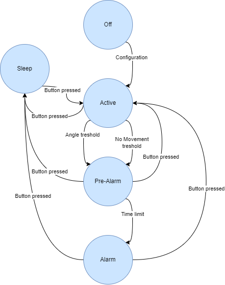
Man down detection
The ioTracker Man Down algorithm (also known as No Movement Algorithm or Lone Worker Safety algrorithm) is built on the following two event triggers:
- Angle: if an employee works mostly upright, a tilted ioTracker indicates an emergency.
- Movement: lack of employee movement indicates an emergency.
Then, by default, Man Down detection behaviour is as follows:
- If either of the two event triggers occur, the ioTracker goes into pre-alarm state and starts beeping the buzzer and blinking the LED.
- Pre-alarm is a grace period of 20 seconds to allow an employee to prevent the ioTracker to send an actual alarm. Moving or getting upright again, or pressing the button, will prevent the alarm.
- The Man Down detection feature can be paused/put in sleep via a long-press, e.g., at the start/end of a shift.
- If Man Down detection feature is enabled (also when paused/put in sleep), always the Man down data is included in the payload.
| Bit position | Default | Description | Application |
|---|---|---|---|
| b0..b3 | 0d0 | State: 0: Active and Ok 1: Sleeping 2: Pre-Alarm 3: Alarm 6..15) RFU |
|
| b4 | 0d0 | Alarm triggered by angle | |
| b5 | 0d0 | Alarm triggered by movement | |
| b6..b7 | 0d0 | RFU |
Flow-chart: Below, an abstract flowchart for state switching is displayed.
Angle sensor
See also Set Advanced Accelerometer tilt configuration
| Byte position | Description | Application |
|---|---|---|
| B01 | Current angle XY 0.01 degrees / lsb |
Resolved tilt (0..180) |
| B2 | 0..120 Current angle Z (360/255) degrees / lsb |
Direction of tilt |
| B34 | Maximum angle history XY 0.01 degrees / lsb |
Maximum since … depending on configuration |
| B5 | 0..120 Maximum angle history Z (360/255) degrees / lsb |
Not the maximum Z but the Z value corresponding to the maximum XY |
Bluetooth
The Bluetooth scan results package content contains the identified Bluetooth Low Energy beacons nearby the ioTracker.
| Bit position | D | Description |
|---|---|---|
| b0..b2 | 0d2 | Number of beacons in this message: 0..7 |
| b3..b4 | 0d0 | 0: BT successful 1: BT failed (chip/power) 2: No beacons found 3: RFU |
| b5..b6 | 0d0 | Add slot info: 0 : 1B for result status + rssi + 6b data 1 : 1B for result status + rssi + full data 2 : 2B for result + slot + rssi + (4B for iBeacon and AltBeacon, 6B for Eddystone) |
| b7 | RFU |
b5 = 0 -> 1B Result status + RSSI
| Bit position | D | Description | Application |
|---|---|---|---|
| b0..b1 | 0d0 | Beacon type: 0: iBeacon 1: Eddystone 2: AltBeacon 3: RFU |
iBeacon (16B UUID + 2B major + 2B minor) Eddystone (10B namespace + 6B instance) AltBeacon (16B id1 + 2B id2 + 2B id3) |
| b2..b7 | 0d0 | RSSI = 27 - ([0..63] * 2) | Internally rounded down (lsb removed) If configured the “Calibrated reference power” information from the beacon is subtracted from this data. The ioTracker should then report 0dB at 1 meter. |
b5 = 1 -> 2B Result status + Slot + RSSI
| Bit position | D | Description | Application |
|---|---|---|---|
| b0..b1 | 0d2 | Beacon type: 0: iBeacon 1: Eddystone 2: AltBeacon 3: RFU |
iBeacon (16B UUID + 2B major + 2B minor) Eddystone (10B namespace + 6B instance) AltBeacon (16B id1 + 2B id2 + 2B id3) |
| b2..b4 | 0d0 | Slot match | Indicates to which slot the data matches |
| b5..b7 | RFU | ||
| b8..b13 | 0d0 | RSSI = 27 – ([0..63] * 2) | Internally rounded down (lsb removed) If configured the “Calibrated reference power” information from the beacon is subtracted to this data. The ioTracker should than report 0dB at 1 meter. |
| b14..b15 | RFU |
RSSI calculation in the ioTracker
Each beacon packet includes the data how strong it is transmitting. With the help of this data we
can correct the result so that a strong transmitting beacon is not perceived closer than a
weak transmitting beacon. If b15 of the Bluetooth scan configuration is set, the ioTracker will
combine and correct the received RSSI with the “calibrated reference power” value the
beacon reports and the ioTracker receive sensitivity.
With correction enabled (b15 ) the:
=
RSSImeasured - BeaconReferenceRSSI + ioTracker calibration correction
If everything is configured correctly the ioTracker should report around the same beacon RSSI as a calibrated phone. A calibrated beacon typically reports an RSSI of -58 at 1 meter.
You should now take extra care of how to configure your beacons. If you set their transmit power to -10dB (e.g., to save power), then also update the field for calibrated power (see Section 8.13) at 1m 10dB lower. e.g. from -58 to -68.
Take precaution setting up an Eddystone beacon, as it is calibrated at 0 centimetre instead of 1 meter. The value in the reference field is 41dB higher compared to an iBeacon. The ioTracker corrects these 41dB already. If you perceive erroneous results, you can disable this function and the raw received RSSI is reported.
GPS
The GPS uplink is included in Uplink payload data when the GPS package content bit is set. The GPS content has a size of 19 bytes.
| Byte position | Type | Description | Decimals | Example | Unit |
|---|---|---|---|---|---|
| B1 | uint8_t | Navigation status (0 = no fix) | 0 | 3 | |
| B2..B5 | int 32b | Latitude of the device in degrees range [−90..90] | 7 | 514498915 | |
| B6..B9 | int 32b | Longitude of the device in degrees range [−180..180] | 7 | 60531326 | |
| B10..B11 | uint16_t | altRef; // altitude above user datum ellipsoid | 1 | 543 | m |
| B12 | uint8_t | hAcc; // horizontal accuracy estimate | 0 | 58 | m |
| B13 | uint8_t | vAcc; // vertical accuracy estimate | 0 | 61 | m |
| B14..B15 | uint16_t | sog; // speed over ground | 1 | 0 | km/h |
| B16..B17 | uint16_t | cog; // course over ground | 1 | 1588 | degrees |
| B18 | uint8_t | hdop; // HDOP, Horizontal Dilution of Precision | 1 | 12 | |
| B19 | uint8_t | numSvs; // number of satellites used in the navigation solution | 0 | 9 |
Attention: latitude and longitude are signed.
For some GPS session ending Navstat 0 is replaced with Navstat 20..25 to give more information about why the GPS session has stopped.
Navstat
| Nr | Code | Description | GPS data/Coordinates valid |
|---|---|---|---|
| 0 | NF | No Fix | No |
| 1 | DR | Dead Reckoning only | Yes |
| 2 | G2 | Stand-alone 2D | Yes |
| 3 | G3 | Stand-alone 3D | Yes |
| 4 | D2 | Differential 2D | Yes |
| 5 | D3 | Differential 3D | Yes |
| 6 | RK | GPS + DR | Yes |
| 7 | TT | Time only | Yes |
| 20 | GPS delayed due to battery | No | |
| 21 | GPS terminated due to battery | No | |
| 22 | GPS terminated due to no initial fix | No | |
| 23 | GPS terminated due to lost fix | No | |
| 24 | GPS terminated due to moving timer | No | |
| 25 | GPS terminated due to static timer | No |
For example: if the device is inside and cannot get a GPS fix, it will try 5 minutes to get a fix, and then report the GPS data with Navstat 22.
Uplink examples
Example 1: 0x03 XX XX (button pressed, moved, no temperature, the rest disabled.)
| Packet | Description | Application |
|---|---|---|
| 2b | Uplink header 0b00 |
Default uplink header |
| 3b | Package content 0b000 |
No on-board sensor data included |
| 3b | Uplink reason 0b011 |
Button pressed (0b001) and moved (0b010) <- XOR'ed |
| 1B | CRC 0xXX |
Any CRC |
| 1B | Battery status 0xXX |
Any battery status |
Example 2: 0x13 XX XX 0307D 01343 (button pressed, moved, precise temperature and light data included, the rest disabled.)
| Packet | Description | Application |
|---|---|---|
| 2b | Uplink header 0b00 |
Default uplink header |
| 3b | Package content 0b010 |
Onboard sensor data included |
| 3b | Uplink reason 0b011 |
Button pressed (0b001) and moved (0b010) <- XOR'ed |
| 1B | CRC 0xXX |
Any CRC |
| 1B | Battery status 0xXX |
Any battery status |
| 1B | Onboard sensor package content 0x03 |
Temperature included (0b000000001) and light included (0b00000010) <- XOR'ed |
| 2B | Temperature data 0x07D0 |
20 degrees Celsius (int16_t 0,01C / LSB) |
| 2B | Light data 0x1343 |
0d0.01 * (0d2^0x1) * 0x343 = 16.70 lux (4b exponent (15..12), 12b unsigned (11..0)) |
Example 3: 0x13 00 F9 1F 07D0 1343 000004000020 00600C80 23 3C77E632E25BAF3E77E632E25CAF4C9EFFFE2FC5A2 (button pressed, moved, precise temperature, light and WiFi data included.)
| Packet | Description | Application |
|---|---|---|
| 2b | Uplink header 0b00 |
Default uplink header |
| 3b | Package content 0b010 |
Onboard sensor data (precise temp and precise light) and GPS data included |
| 3b | Uplink reason 0b011 |
Button pressed (0b001) and moved (0b010) <- XOR'ed |
| 1B | CRC 0x00 |
00 CRC |
| 1B | Battery status 0xF9 |
249 ~= 98% |
| 1B | Onboard sensor package content 0x1F |
Temperature included (0b000000001), light included (0b00000010), accelerometer current included (0b00000100), accelerometer max included (0b00001000), WiFi included (0b00010000) <- XOR'ed |
| 2B | Temperature data 0x07D0 |
20 degrees Celsius (int16_t 0,01C / LSB) |
| 2B | Light data 0x1343 |
0d0.01 * (0d2^0x1) * 0x343 = 16.70 lux (4b exponent (15..12), 12b unsigned (11..0)) |
| 6B | Accelerometer current data 0x000004000020 |
0x0000 | | 0x0400 | | 0x0020 = 0 mg on x-axis | | 1024 mg on y-axis | | 32 mg on z-axis |
| 2B | Accelerometer max data 0x00600C80 |
0x0060 | | 0x0c80 = 0d96 | | 0d3200 = 96 mg max since previous uplink | | 3.2 g max of all previous 16 uplinks |
| 1B | 0x23 | WiFi RSSI included, 3 Wi-Fi mac addresses found |
| 21B | 0x3C77E632E25BAF3E77E632E25CAF4C9EFFFE2FC5A | 3C:77:E6:32:E2:5B with RSSI of (0xAF=-81) 3E:77:E6:32:E2:5C with RSSI of (0xAF=-81) 4C:9E:FF:FE:2F:C5 with RSSI of (0xA2=-94) |
Example 4: 0x1B DD 64 1F 075F 44A0 000004000020 00600C80 00031EAB10B0039C7275031F1315000400002705 (button pressed, moved, precise temperature, light and GPS data included.)
| Packet | Description | Application |
|---|---|---|
| 2b | Uplink header 0b00 |
Default uplink header |
| 3b | Package content 0b011 |
Onboard sensor data (precise temp and precise light) and GPS data included |
| 3b | Uplink reason 0b011 |
Button pressed (0b001) and moved (0b010) <- XOR'ed |
| 1B | CRC 0xDD |
DD CRC |
| 1B | Battery status 0x64 |
0d100 ~= 40% (100/254) |
| 1B | Onboard sensor package content 0x1F |
Temperature included (0b000000001), light included (0b00000010), accelerometer current included (0b00000100), accelerometer max included (0b00001000), WiFi included (0b00010000) <- XOR'ed |
| 2B | Temperature data 0x075F |
18,87 degrees Celsius (int16_t 0,01C / LSB) |
| 2B | Light data 0x44A0 |
0d0.01 * (0d2^0x4) * 0x4A0 = 189.44 lux (4b exponent (15..12), 12b unsigned (11..0)) |
| 6B | Accelerometer current data 0x000004000020 |
0x0000 | | 0x0400 | | 0x0020 = 0 mg on x-axis | | 1024 mg on y-axis | | 32 mg on z-axis |
| 2B | Accelerometer max data 0x00600C80 |
0x0060 | | 0x0c80 = 0d96 | | 0d3200 = 96 mg max since previous uplink | | 3.2 g max of all previous 16 uplinks |
| 1B | GPS data 0x03 1EAB10B0 039C7275 031F 13 15 0004 0000 27 05 |
1B Navstat = 0x03 = ok/got a GPS fix correctly 4B LAT = 0x1eab10b0 = 51.4527408 4B LON = 0x039c7275 = 6.0584565 2B 0x039c7275 = 6.0584565 = 0x031f = 79.9m 1B horizontal accuracy m = 0x13 = 19 m 1B vertical accuracy m = 0x15 = 21 m 2B speed over ground = 0x0004 = 0.4 km/h 2B course over ground = 0x0000 = 0 degree 1B hdop = 0x27 = 3.9 1B #satellites found = 0x05 = 5 satellites |